
Where we think, talk, and test
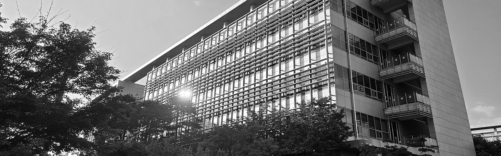
The lab is housed in the Renewable Energy Research Building (C10) on the GIST campus, with separate rooms for desk work, meetings, and experiments. A proposed method is not considered finished until it has been demonstrated with experimental results, at laboratory scale or beyond. The rooms and the equipment in them are shown below.
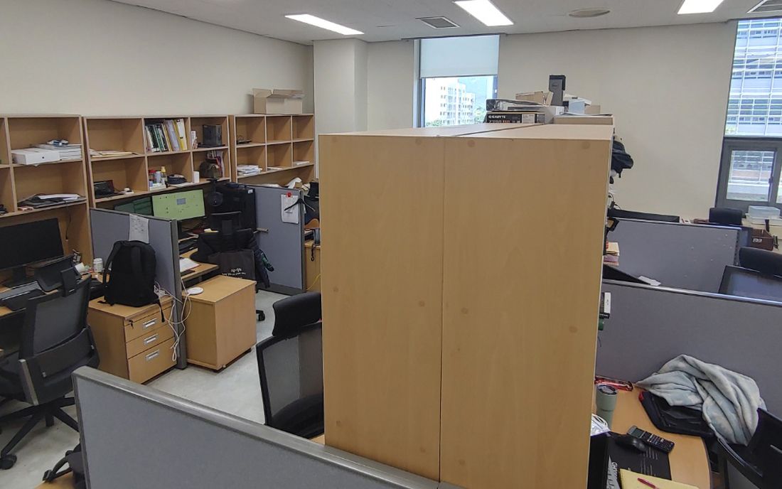
Study room — A desk, a PC, and two monitors for each member. Licensed software includes MATLAB, PLECS, Altium, OrCAD, Ansys Electronics, Vivado, and Mathematica.
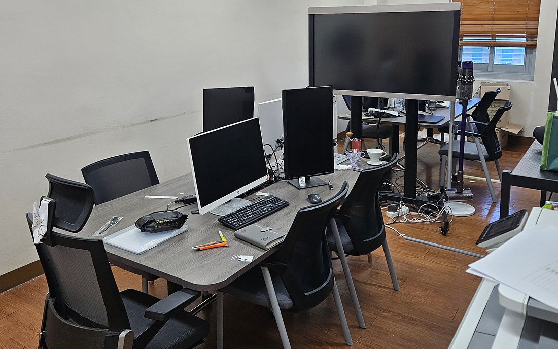
Multipurpose room — Meetings, seminars, and calls happen here, around an interactive whiteboard. Each member has a cabinet, and an all-in-one PC gives remote access to the machines in the study and experiment rooms. A fridge, a microwave, and a Nespresso machine keep people from having to leave.
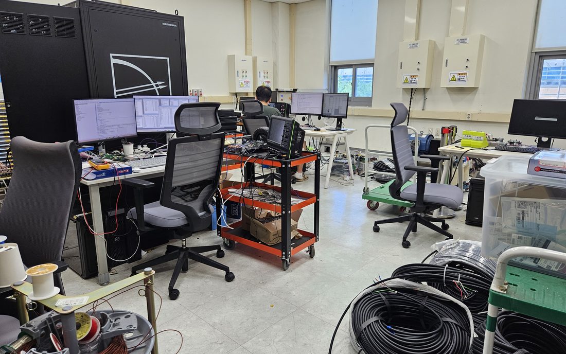
Experiment room 1 — Grid-connected inverter benches, a hardware-in-the-loop bench built around a real-time simulator, an ESS cabinet, and a motor–generator set. Experiments up to 32.9 kW run here.
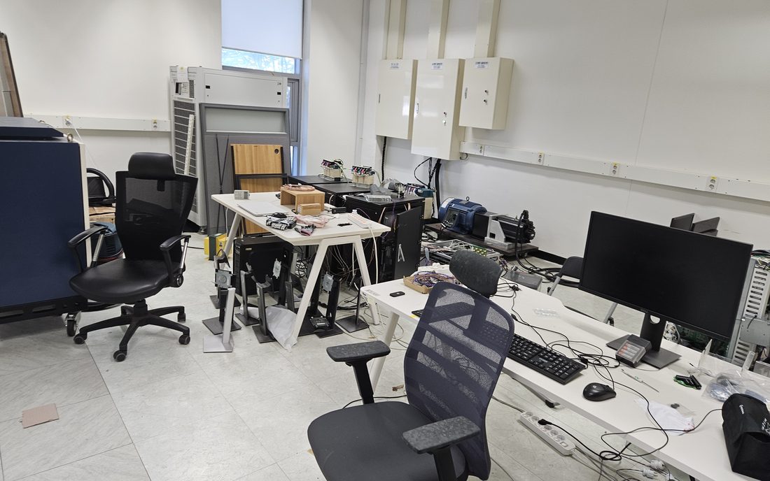
Experiment room 2 — A larger room shared with other groups; our part is for grid experiments. The grid simulator lives here, wired through to the first experiment room, along with a second motor–generator set and a multichannel measurement system based on NI DAQ hardware.
Principal systems
Real-time simulator
OPAL-RT OP5030 with OP5607 expansion
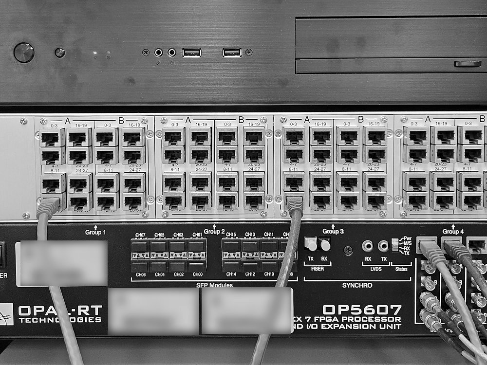
The hardware-in-the-loop bench is built around this pair. The expansion unit carries a Virtex-7 485T FPGA, eight mezzanine slots, 256 I/O lines and sixteen SFP links at up to 5 Gbps, so a controller can be tested against a simulated grid at converter switching rates before it is wired to real hardware.
Real-time target machine
Speedgoat Performance, with IO334-325k, -21, IO755 and IO756 modules
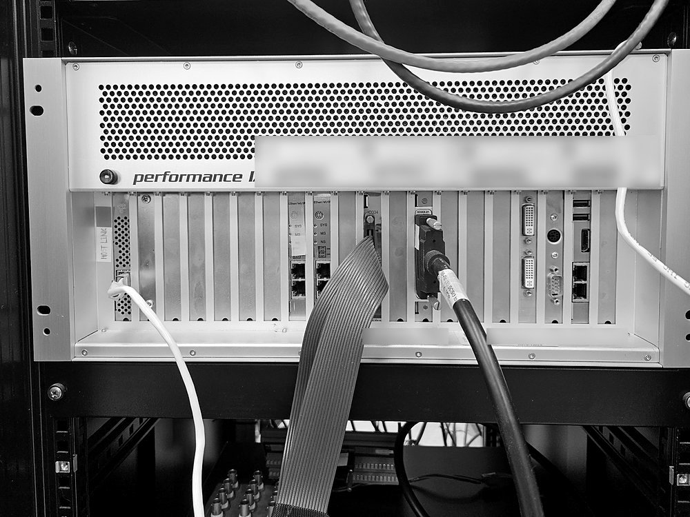
A second real-time path, used for rapid control prototyping straight from Simulink. The Performance chassis holds the multi-core CPU and the modules that reach the hardware: an IO334 carrying a Kintex-7 XC7K325T FPGA, with sixteen analogue inputs and sixteen analogue outputs at 16 bits and 5 MS/s; a -21 interface extension in a slot of its own, adding 56 configurable single-ended TTL lines for pulse, encoder, SPI and I²C work; and IO755 and IO756 modules for EtherNet/IP scanner and adapter interfaces.
Regenerative grid simulator
Chroma 61830, 30 kVA
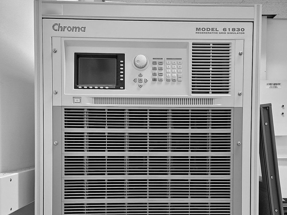
A four-quadrant AC source and sink, 0–300 V line to neutral, 50 A per phase, 30–100 Hz. It sets the grid conditions a grid-connected inverter has to ride through — sags, harmonics, frequency excursions — and returns the power it absorbs to the mains instead of burning it.
High-definition oscilloscope
Teledyne LeCroy WaveRunner 8108HD
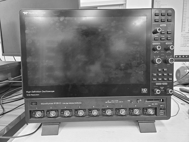
Eight channels at 12-bit resolution and 1 GHz bandwidth. Signals that would otherwise take several captures to correlate can be recorded at once.
Instruments
- Sources and loads
DC power supplyAmetek Sorensen SGI600/33
0–600 V, 0–33 A, 20 kW programmable, three-phase input, constant voltage or constant current
DC power supplyTOYOTECH DP30-05TP
Triple output, two channels of 0–30 V / 0–5 A plus a fixed 5 V / 1 A rail, 300 W
Variable auto-transformerSlide-AC, 30 kVA
Three-phase, 380 V input, 0–430 V adjustable output, 50/60 Hz
- Control
Rapid-prototyping controllerimperix B-Box RCP 3.0
250 kHz maximum control frequency, sixteen optical PWM channels, sixteen 16-bit 500 kS/s analogue inputs, Zynq-7030 and Kintex-7 FPGA
- Measurement
OscilloscopeTeledyne LeCroy HDO6054A and HDO6054A-MS
500 MHz, 10 GS/s, four analogue channels at 12 bits, sixteen digital channels on the -MS
OscilloscopeRohde & Schwarz RTE1054
500 MHz, 5 GS/s, four channels, 8-bit converter and 16 bits in high-definition mode
Power analyzerYokogawa WT1806E
Six elements, DC to 1 MHz, 2 MS/s at 16 bits, ±0.05 % basic accuracy, harmonics to the 500th
High-voltage differential probeTeledyne LeCroy HVD3106A
120 MHz, 1500 V differential, 1000 V rms CAT III, 50× and 500× attenuation
High-voltage differential probeRohde & Schwarz RT-ZD01
100 MHz, ±1400 V differential and common mode, 100:1 and 1000:1 attenuation
Current probeTeledyne LeCroy CP150
10 MHz, 150 A rms continuous, 500 A peak, 20 mm maximum conductor
Thermal imaging cameraFLIR E75
320 × 240 infrared, under 40 mK NETD, −20 to +650 °C, 24° × 18° field of view at 30 Hz
CompactDAQ chassisNI cDAQ-9174
Four slots, USB 2.0 Hi-Speed, four 32-bit general-purpose counter-timers
Analogue input moduleNI-9205
32 single-ended or 16 differential inputs, 16 bits, 250 kS/s aggregate, ±200 mV to ±10 V
Waveform generatorSiglent SDG1032X
30 MHz, 150 MSa/s, two channels, 14-bit vertical resolution
Waveform generatorRigol DG1032Z
30 MHz, 200 MSa/s, two channels, 14-bit vertical resolution